 English
 عربي
 Русский
 Français
 Español
 Deutsch
قم بزيادة نطاق اتصالك إلى أقصى حد باستخدام جهاز إعادة الإرسال الرقمي DM-5300، الذي يتميز بقدرة عالية تبلغ 40 وات، وتقنية TDMA ذات الفتحة الزمنية المزدوجة، والتحويل الهجين السلس بين الإشارات التناظرية والرقمية لشبكات الراديو الاحترافية.
اقرأ المزيد


DMR Digital Repeater 1-to-4 Optical Fiber Distributed Coverage System (DAS): Engineering Design & Technical Solution Proposal
Have you ever encountered a mission-critical wireless communications blackout inside deep underground utility tunnels, multi-level reinforced concrete basements, or across expansive petrochemical refineries? In massive industrial facilities, traditional coaxial feeder networks experience catastrophic RF signal attenuation—typically shedding 7 to 9 dB per 100 meters at UHF frequencies. Attempting to bridge distant coverage zones using bulky 7/8" or 1-1/4" coaxial cables inevitably leads to dropped PTT calls, severe audio packet loss, exorbitant copper cabling expenses, and severe base station receiver desensitization.
To overcome these physical propagation barriers, KANGLONG ELECTRON. TECH. CO., LTD. has engineered the DMR Digital Repeater 1-to-4 Optical Fiber Distributed Antenna System (DAS). By converting radio frequency (RF) signals into optical carriers transported over standard single-mode fiber optic cabling (exhibiting a negligible loss of ≤ 0.35 dB/km), this active star-distributed architecture extends seamless, crystal-clear 2-slot TDMA digital communications up to 10 to 20 kilometers across 4 discrete remote zones using just one central DMR repeater base station.
Compliant with the ETSI DMR Tier II / Tier III digital mobile radio open standards, this 1-to-4 active DAS distribution architecture delivers enterprise-grade wireless coverage across demanding industrial environments without requiring redundant frequency license allocations:
The complete system integrates three functional layers: the Central Equipment Room (DMR Repeater + Optical Master Unit + Master Cavity Duplexer + Base Station Local Antenna), the Optical Transport Subsystem (4 single-mode fiber links), and 4 Remote Coverage Zones (Optical Remote Units 1#~4# + distributed indoor/outdoor antennas).
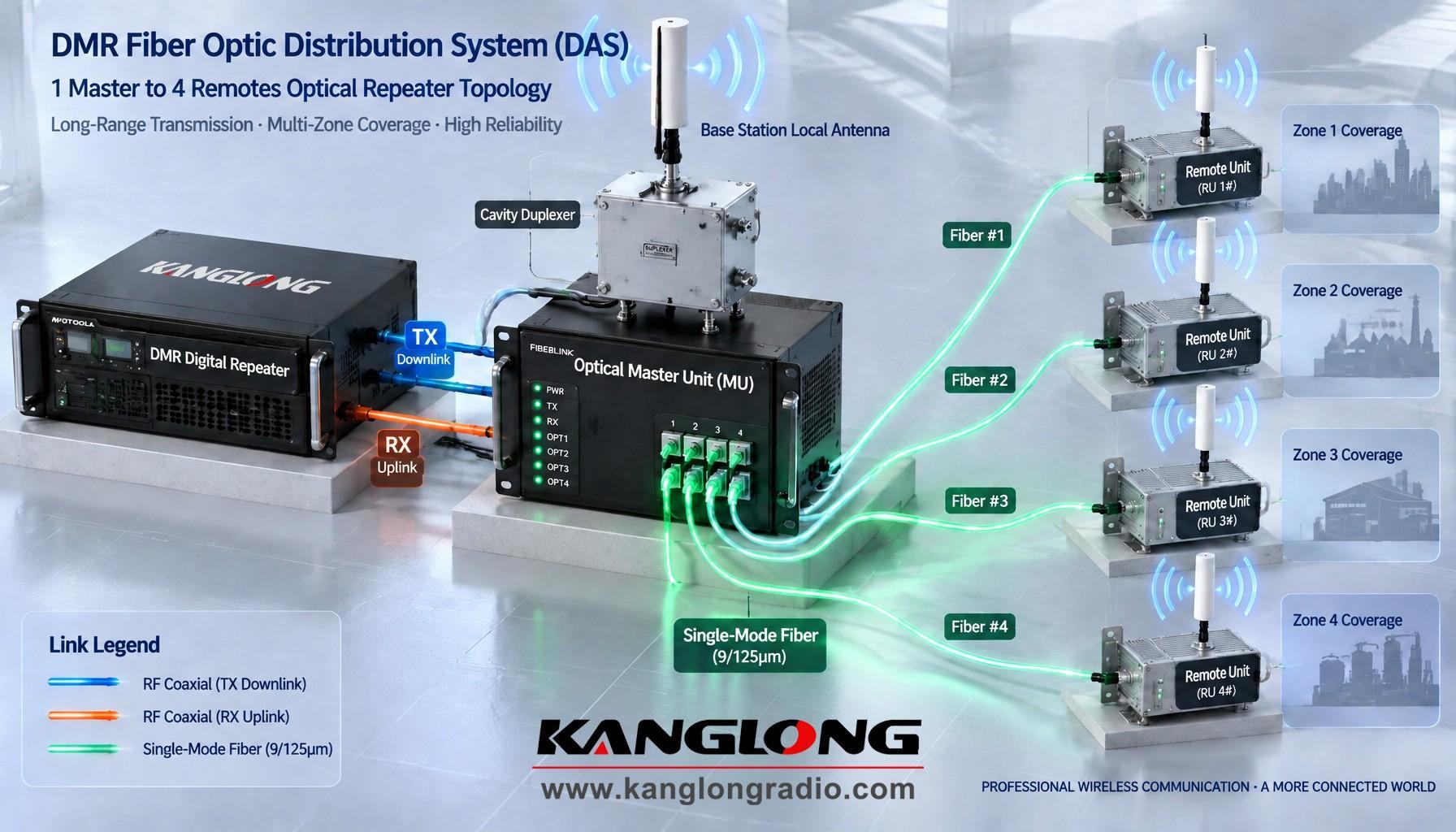
Figure 2-1: 3D System Topology of DMR Digital Repeater 1-to-4 Optical Fiber Distributed Coverage System (DAS)
| # | System Component | Key Technical Specifications | Qty | Deployment Site |
|---|---|---|---|---|
| 1 | DMR Digital Repeater | UHF 400-470 MHz / VHF 136-174 MHz; ETSI DMR Tier II/III, 2-Slot TDMA; RF Power: 25W~50W; RX Sensitivity: -120 dBm; Connectors: N-Female, RJ45 IP | 1 Unit | Central Equipment Rack |
| 2 | Optical Master Unit (MU) | 19-inch 2U/3U Rackmount; 4-Way FC/APC or SC/APC Optical Ports; RF Input Handling: 0~+43 dBm; Dynamic Range ≥ 60 dB; Local Duplexer Port; Web/SNMP NMS | 1 Unit | Central Equipment Rack |
| 3 | Optical Remote Unit (RU) | Outdoor Die-Cast Wall-Mount (IP65 / NEMA 4X); RF Output: 5W / 10W / 20W; Integrated Cavity Duplexer (Isolation ≥ 80 dB); Gain Range: 31 dB (1 dB step), ALC/AGC; Surge: 6 kV | 4 Units | Remote Zones 1# ~ 4# (IDF / Wall Mount) |
| 4 | Master Cavity Duplexer | Frequency Separation: 5 MHz (UHF) / 5.7 MHz (VHF); Power Handling ≥ 100W; Insertion Loss ≤ 1.0 dB; TX/RX Isolation ≥ 80 dB | 1 Unit | Central Equipment Rack |
| 5 | Antenna & Feeder System | Outdoor: High-Gain Fiberglass Omni (7-9 dBi) / Directional Panel (11-14 dBi); Indoor: Ceiling Omni (3-5 dBi); 1/2" Low-Loss Coax, Surge Arrestors | 5 Sets | Master Base + 4 Remote Sites |
| 6 | Optical Fiber Backbone | Single-Mode G.652D 9/125 μm (8-12 Core Armored Backbone); Optical Distribution Frame (ODF), Connector Insertion Loss ≤ 0.3 dB | 1 Lot | Cable Trays / Conduits |
DMR 2-slot TDMA operates on a 30 ms frame structure with a 2.5 ms (2,500 μs) Guard Interval between slots. Light propagates through single-mode fiber at approximately 200,000 km/s (5 μs/km). Over a 10 km optical link, one-way fiber propagation delay is precisely 50 μs (0.05 ms), consuming just 2% of the DMR guard window. This wide safety margin guarantees zero time-slot collisions or synchronization slips across the distributed network.
In a 1-to-4 active star topology, passively combining 4 unmanaged optical return paths increases the repeater receiver noise floor by:
ΔN = 10 × log10(4) ≈ 6.02 dB
Left unchecked, a 6 dB noise penalty cuts the central repeater receiver sensitivity by 50%. The KANGLONG Master Unit eliminates this via Smart Carrier-Operated Squelch Gating: idle optical channels are dynamically clamped by ≥ 30 dB, instantly unmuting in < 1 ms only upon detecting active carrier RF energy.
The Master Unit DFB optical transmitter delivers launch power of 0 to +3 dBm, while RU receiver sensitivity is rated at -15 dBm, yielding an available optical loss budget of ≥ 15 dB. For a typical 10 km single-mode run (total fiber attenuation ~3.5 dB + 1.4 dB connector/splice loss = 4.9 dB), the system maintains a robust > 10 dB optical safety margin against fiber aging and micro-bends.
[Phase 1: Fiber Validation] → [Phase 2: RF Power Calibration] → [Phase 3: RU Output & VSWR Tuning] → [Phase 4: DMR Protocol Acceptance]
| Symptom | Root Cause Analysis | Corrective Action |
|---|---|---|
| Downlink OK, but Radios Cannot Access Repeater (Uplink Failure) | 1. RU uplink gain set too low 2. Master Unit optical RX module faulted 3. Excessive local RF noise floor in target zone |
1. Increase RU uplink gain via digital step attenuator (decrease ATT). 2. Inspect optical RX status LED on Master Unit front panel. 3. Sweep local spectrum to locate co-channel RF interference. |
| Muffled Audio / High Bit Error Rate (BER) | 1. Laser diode overdriven into non-linear clipping distortion 2. Contaminated optical connectors causing high optical return loss (ORL) |
1. Increase TX attenuation on Master Unit input to lower modulation depth. 2. Clean all SC/FC fiber ferrule endfaces with optical-grade alcohol wipes. |
| Repeater Base Receiver Desensitization | Cumulative uplink noise from multiple unmuted RUs or RU PA self-oscillation due to high VSWR | Sequentially disconnect optical fiber ports at the Master Unit to isolate the offending noisy branch. Verify antenna feeder VSWR (≤ 1.4). |
| Optical Alarm LED Illuminated on Master Unit | Optical fiber break, excessive fiber link attenuation (> 15 dB), or Remote Unit AC/DC power loss | Measure received optical power at RU with optical power meter; check fiber patch cords and verify remote power supply voltage. |
Answer: Under the ETSI DMR standard, each 30 ms TDMA frame incorporates a 2.5 ms (2,500 μs) Guard Interval between Slot 1 and Slot 2 to absorb propagation delays. Since optical signals travel through single-mode fiber at ~5 μs per kilometer, a 20 km fiber run induces only a 100 μs one-way propagation delay—amounting to just 4% of the guard interval. Consequently, optical fiber latency will not cause TDMA time-slot overlap or frame decoding loss up to 20 to 30 kilometers. For systems exceeding 30 km or with extreme differential lengths between branches, the KANGLONG Master Unit integrates dynamic digital buffer delay compensation to maintain strict symbol synchronization.
Answer: In conventional analog fiber repeaters, combining N optical return channels causes an unmitigated noise floor rise of ΔN = 10×log10(N) (approx. 6 dB for 4 channels), severely degrading base repeater receiver sensitivity. The KANGLONG Optical Master Unit solves this through Intelligent Carrier-Operated Squelch Gating. When no handheld radio is transmitting in a given remote zone, that specific optical receiver path is automatically clamped by ≥ 30 dB. The squelch gate detects valid RF bursts and un-mutes in less than 1 millisecond, ensuring that only active channels contribute to the uplink combiner, keeping the base station noise floor completely quiet.
Answer: Feeding a 45 dBm (30W) or 47 dBm (50W) repeater output directly into an electro-optical conversion module would instantly overdrive the DFB laser into severe non-linear clipping, generating third-order intermodulation distortion (IMD3) and corrupting digital 4FSK constellation points. The KANGLONG Master Unit includes an integrated high-power 50W RF attenuator and digital step attenuators (0~31 dB, 1 dB steps). During commissioning, technicians calibrate the input attenuation so the internal RF drive level reaches the optimal linear Optical Modulation Index (OMI) window between 0 dBm and +10 dBm, guaranteeing maximum dynamic range and minimal Error Vector Magnitude (EVM < 3%).
Answer: When a portable two-way radio operates in a boundary area covered simultaneously by RU #1 (e.g., 2 km fiber) and RU #2 (e.g., 8 km fiber), the 6 km fiber difference introduces a ~30 μs arrival time discrepancy. In digital DMR 4FSK systems, delay differentials under 50 μs generally fall within the receiver equalizer capture capability. However, to eliminate delay-spread distortion and inter-symbol interference (ISI) in high-density areas, the KANGLONG system utilizes Digital Delay Equalization in the Master Unit to delay shorter fiber paths, aligning RF arrival times at overlap boundaries to within < 5 μs.
Answer: KANGLONG Optical Remote Units are engineered for harsh industrial environments, featuring a die-cast aluminum IP65 / NEMA 4X weather-sealed enclosure with natural convection cooling fins (no failure-prone mechanical fans). The internal power subsystem supports wide AC input (100-240V AC, 50/60 Hz) or industrial DC -48V power with integrated 6 kV lightning surge protection (IEC 61000-4-5 standard). All RF ports feature built-in DC blocks and gas-discharge surge arrestors, operating reliably across extreme temperature ranges from -30°C to +60°C.
Answer: Yes. The KANGLONG optical distribution platform is modular and scalable. By cascading Optical Master Units or deploying multi-channel optical transceivers with Wavelength Division Multiplexing (CWDM / DWDM), a single fiber core can carry multiple frequency bands (e.g., VHF 136-174 MHz + UHF 400-470 MHz or dual-carrier DMR Tier III trunking). Furthermore, the architecture seamlessly accommodates PoC (Push-to-Talk over Cellular) gateway integration, enabling unified hybrid dispatching between private DMR repeater networks and nationwide public cellular radios.
KANGLONG ELECTRON. TECH. CO., LTD. is a premier manufacturer and international turnkey solution provider specializing in professional two-way radio hardware, digital DMR/PoC trunking systems, Distributed Antenna Systems (DAS), and mission-critical RF repeater networks. From customized system link budgeting and RF coverage simulation to OEM/ODM equipment manufacturing, KANGLONG empowers global telecom contractors, industrial fleets, and security organizations with resilient wireless communication infrastructure.
Company: KANGLONG ELECTRON. TECH. CO., LTD.
Official Website: www.kanglongradio.com
LinkedIn: linkedin.com/company/105964174
Facebook: facebook.com/grant.chen.2025
Instagram: @kanglonggrant

قم بزيادة نطاق اتصالك إلى أقصى حد باستخدام جهاز إعادة الإرسال الرقمي DM-5300، الذي يتميز بقدرة عالية تبلغ 40 وات، وتقنية TDMA ذات الفتحة الزمنية المزدوجة، والتحويل الهجين السلس بين الإشارات التناظرية والرقمية لشبكات الراديو الاحترافية.
اقرأ المزيد